Simulation-led lightweighting of a gearbox shift fork through
non-linear FEA, design iteration, convergence and analytical validation.
01
ENGINEERING QUESTION
How can a gearbox shift fork be redesigned to significantly reduce
mass while maintaining sufficient strength, stiffness and realistic
load transfer?
The study uses finite element analysis to understand the structural
behaviour of the component, progressively refine its geometry and
identify a lightweight design that remains within the defined
operating constraints.
PRIMARY OBJECTIVEMinimise mass without compromising structural performance
03
METHODOLOGY
01BASELINE MODEL
Define geometry, material and functional constraints.
→
02FEA SETUP
Apply constraints, contact, load and mesh strategy.
→
03ANALYSIS
Compare linear and non-linear structural response.
→
04ITERATE
Remove material based on stress and deflection behaviour.
→
05VALIDATE
Mesh convergence, static checks and dynamic comparison.
04
INITIAL ANALYSIS
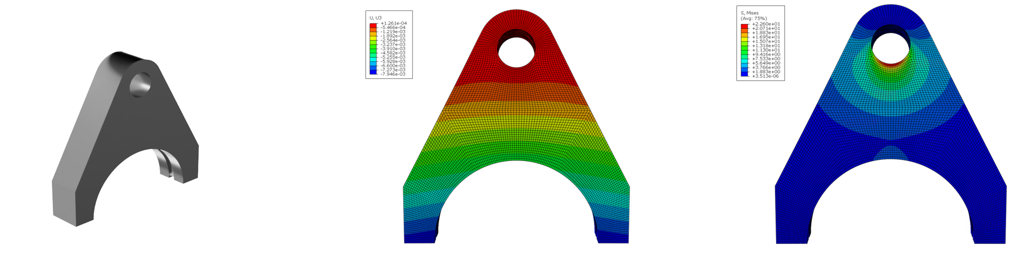
Initial geometry and baseline structural response
The initial 1.28 kg design was first assessed using linear analysis
before introducing non-linear contact. The non-linear model was
considered more representative because the applied load was
transferred through contact with a massless rigid ring rather than
through a uniformly distributed pressure.
Analysis
Max Stress
Max Deflection
Linear
29.51 MPa
0.0155 mm
Non-Linear
22.26 MPa
0.00794 mm
05
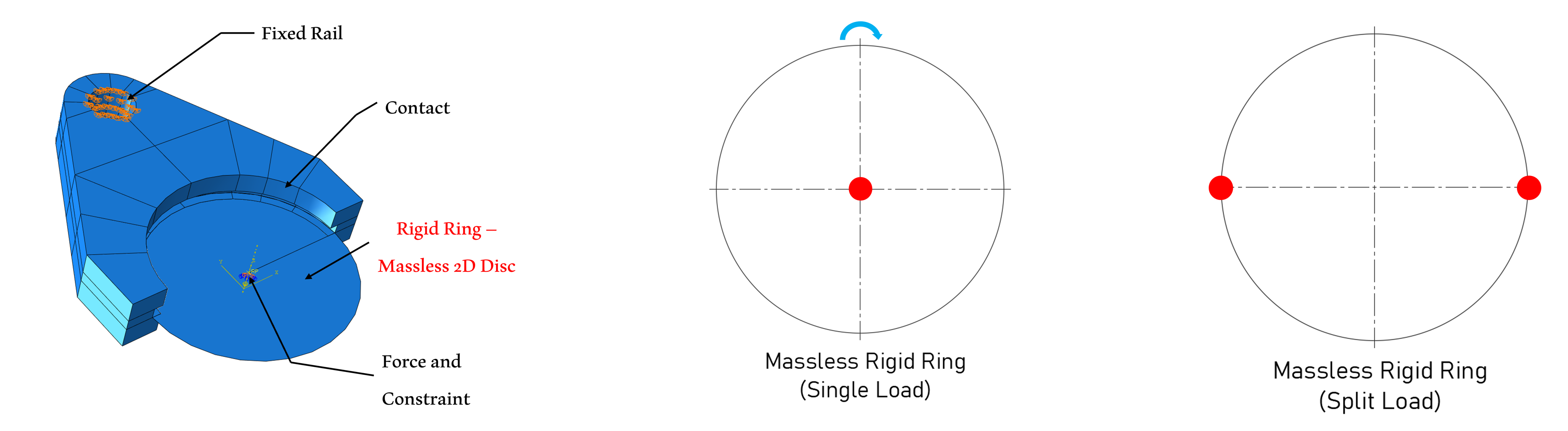
BOUNDARY CONDITIONS
The rail mounting was fixed while a massless rigid ring represented
the gearbox interface. This enabled the force to be introduced
through contact and allowed the influence of contact position and
resulting turning moment to be studied.
Development of the load application methodology
06
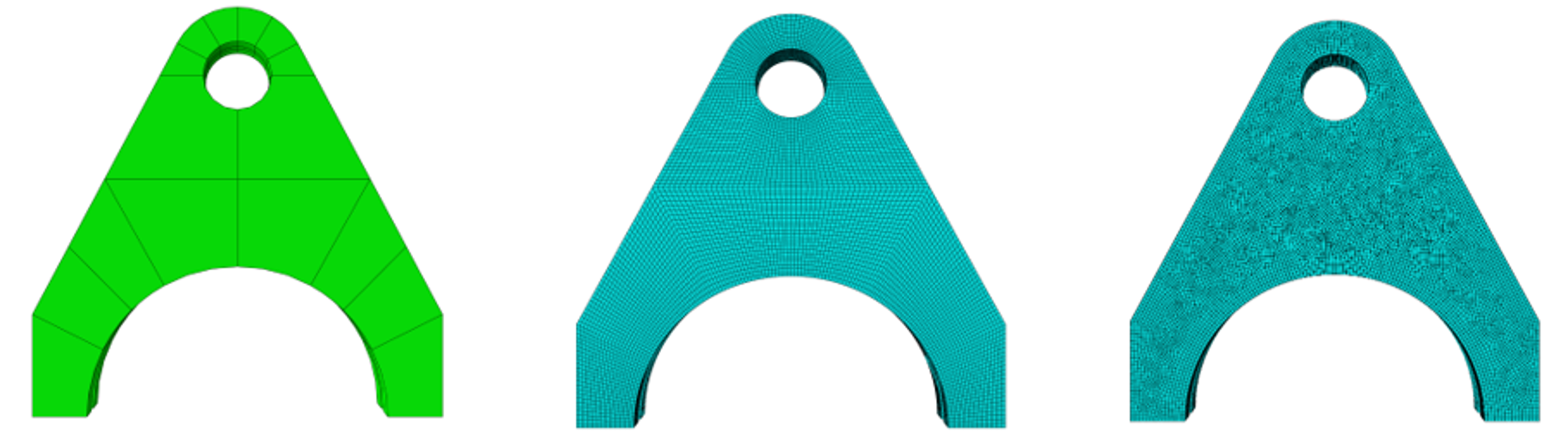
MESH DEVELOPMENT
Structured partitioning reduced the original swept-mesh node count
while improving regularity and numerical stability. Final convergence
was then assessed using quadratic tetrahedral elements with
progressively smaller seed sizes.
Partitioning and mesh strategy
07
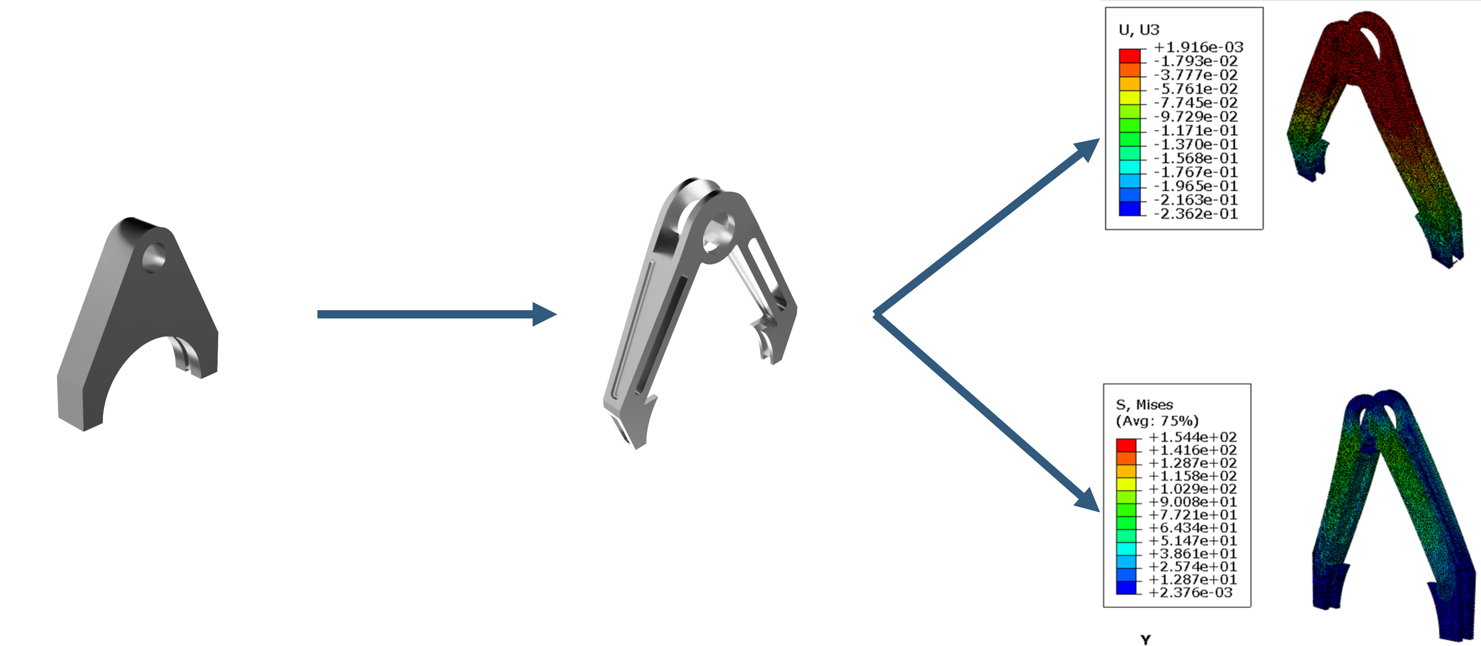
DESIGN ITERATION
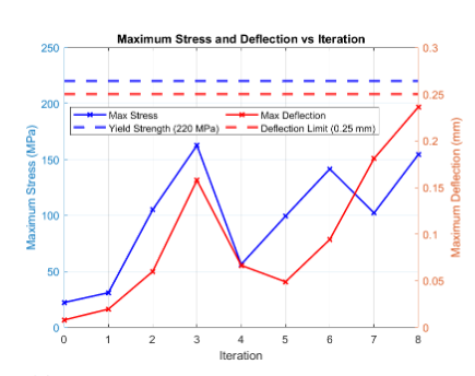
Eight reported iterations progressively removed material from
low-stress regions while monitoring stress, displacement and contact
behaviour. The methodology itself also evolved when the original
contact model produced an unrealistic turning moment.
Representative evolution from baseline geometry to final design
INITIAL MASS1.28 kg
FINAL MASS0.199 kg
84.4%MASS REDUCTION
08
MESH CONVERGENCE
Maximum stress began to stabilise at approximately
1.5 × 10⁵ nodes. Deflection remained effectively constant
throughout refinement, while further refinement was constrained by
the educational licence node limit.
Node count against maximum stress and displacement
09
STATIC VALIDATION
The final fork was simplified to a cantilever-beam representation
to independently check displacement and bending stress.
ymax =
Pa3
/
6EI
(3L/a − 1)
σ =
My / I
ANALYTICAL DEFLECTION0.1764 mm
ANALYTICAL STRESS119.4 MPa
STRESS DISCREPANCY25.57%
10
DYNAMIC ANALYSIS
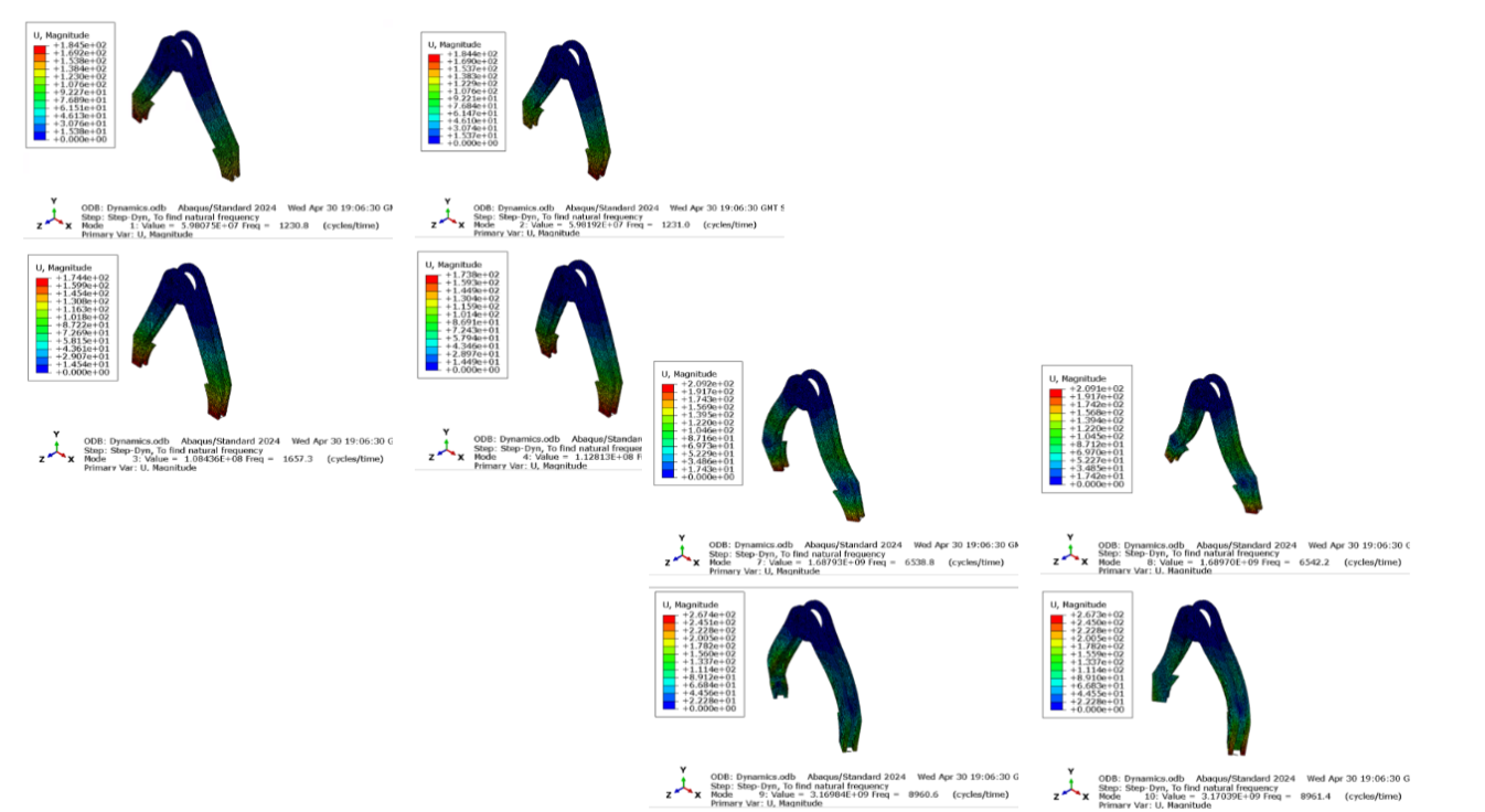
A linear dynamic analysis using the Lanczos algorithm extracted the
ten lowest eigenvalues. Mode 3 was identified as the dominant mode
from its effective mass, with a natural frequency of 1657.3 Hz.
keq = F / ymax
f =
1 / 2π √(keq / m)
FEA MODE 31657.3 Hz
1-DOF ESTIMATE953.14 Hz
DISCREPANCY53.95%
Mode 3 dynamic response
11
KEY TAKEAWAYS
01
SIMULATION-LED LIGHTWEIGHTING
An 84.4% mass reduction was achieved through iterative geometry
development while remaining within the deflection limit.
02
METHODOLOGY MATTERS
Revising the contact representation was necessary when the
original load application produced unrealistic behaviour.
03
VALIDATION DEFINES CONFIDENCE
Analytical checks exposed the limitations of simplified static
and dynamic representations rather than being treated as exact matches.
“The most valuable part of the project was not simply reducing mass,
but understanding how modelling assumptions, contact behaviour,
convergence and validation influence the confidence placed in an
optimised design.”