Concept
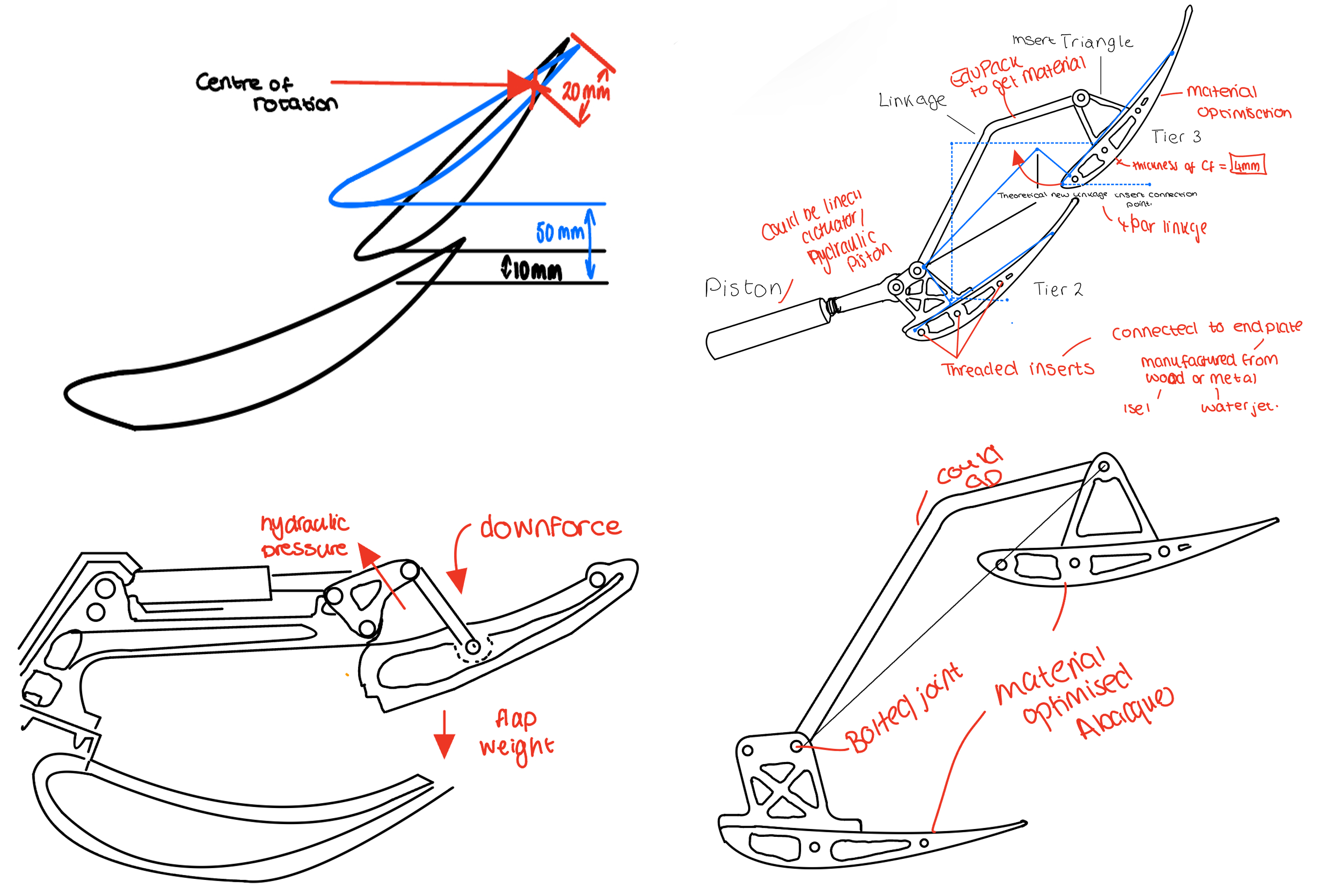
Explore different mechanical layouts and define the required motion of the rear-wing flap.

DESIGN · MECHANISMS · DEVELOPMENT
Developing a scaled Formula One-inspired rear wing and Drag Reduction System from first principles.
PROJECT OVERVIEW
This project explores the design and manufacture of a scaled rear wing and Drag Reduction System, developed from an initial mechanical concept into a functional 3D assembly.
The system was initially considered using either pneumatic actuation or an electrical linear actuator, with the aim of creating a mechanism capable of controlling rear-wing movement.
The project focuses on understanding the underlying mechanics of the system, including component interaction, motion, force transmission and structural behaviour.
DEVELOPMENT PROCESS
Explore different mechanical layouts and define the required motion of the rear-wing flap.
Develop linkages and actuation concepts capable of controlling the flap position.
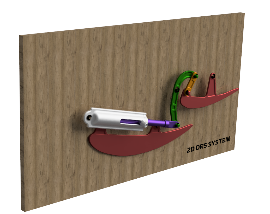
Convert the concept into a 3D-printable model to investigate component interaction and motion.
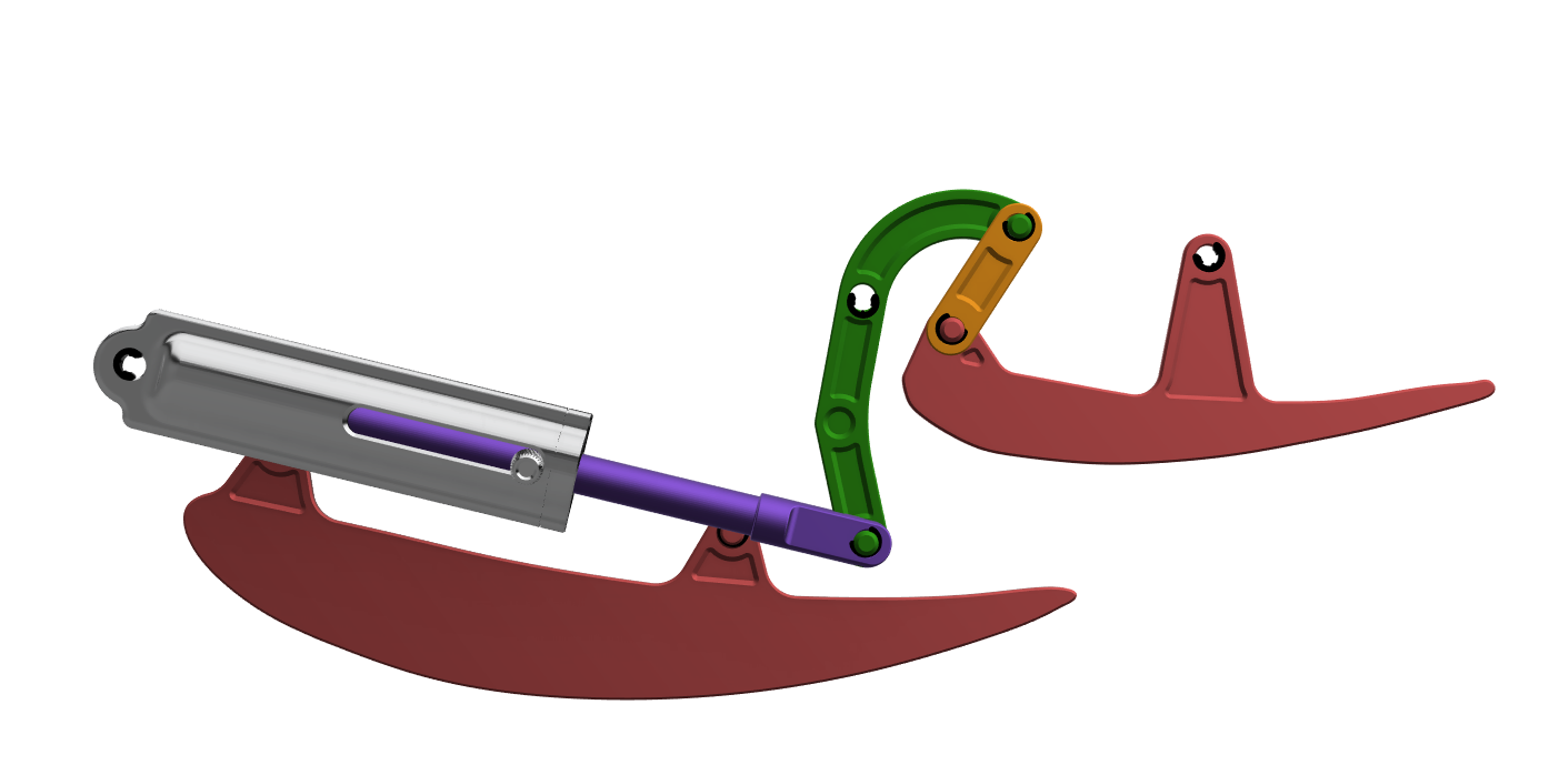
Refine the CAD model to understand load paths, force transmission and structural requirements.
01
CONCEPT DEVELOPMENT
The project began by exploring a range of possible mechanical layouts for actuating a rear-wing flap.
DESIGN INTENT
02
PROTOTYPE DEVELOPMENT
The initial 2D concept was developed into a fully 3D-printable model to better understand the behaviour of the complete mechanism.
03
SYSTEM ARCHITECTURE
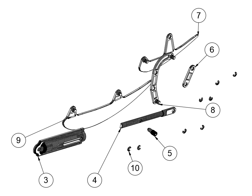
Breaking the mechanism into individual components helped define how each part interfaces with the wider system and highlighted the relationship between the actuator, linkages, flap and mounting structure.
04
ENGINEERING DEVELOPMENT
A more detailed CAD model was developed to move beyond basic mechanism visualisation and begin assessing the system in a three-dimensional engineering environment.
CURRENT DEVELOPMENT
The 3D system remains under development, with further refinement planned as the mechanical design, actuation strategy and structural requirements are developed.
PROJECT REFLECTION
This project has developed my understanding of mechanical systems by requiring the movement of multiple components to be considered together rather than independently.
Progressing from sketches to a 3D-printable mechanism and then to a more detailed CAD assembly has provided a structured approach for understanding motion, packaging and load transfer.