Define
Establish suspension architecture, packaging constraints and required pick-up points.

DESIGN · ANALYSIS · OPTIMISATION
First-principles suspension development combining mathematical modelling, parametric CAD, structural analysis and component design.
PROJECT OVERVIEW
The project focused on the design and development of a rear suspension system for a performance vehicle.
Mathematical modelling was used to optimise suspension geometry and pick-up point locations, supported by finite element analysis and thermal simulation to assess structural performance and brake heat dissipation.
The final design combined suspension kinematics, structural efficiency, packaging and manufacturability into a fully integrated rear suspension assembly.
DEVELOPMENT PROCESS
Establish suspension architecture, packaging constraints and required pick-up points.
Develop mathematical models describing suspension geometry and component behaviour.
Use MATLAB-based optimisation to investigate geometry and loading configurations.
Apply structural and thermal simulation before integrating components into the final assembly.
01
KINEMATICS & PARAMETRIC DESIGN
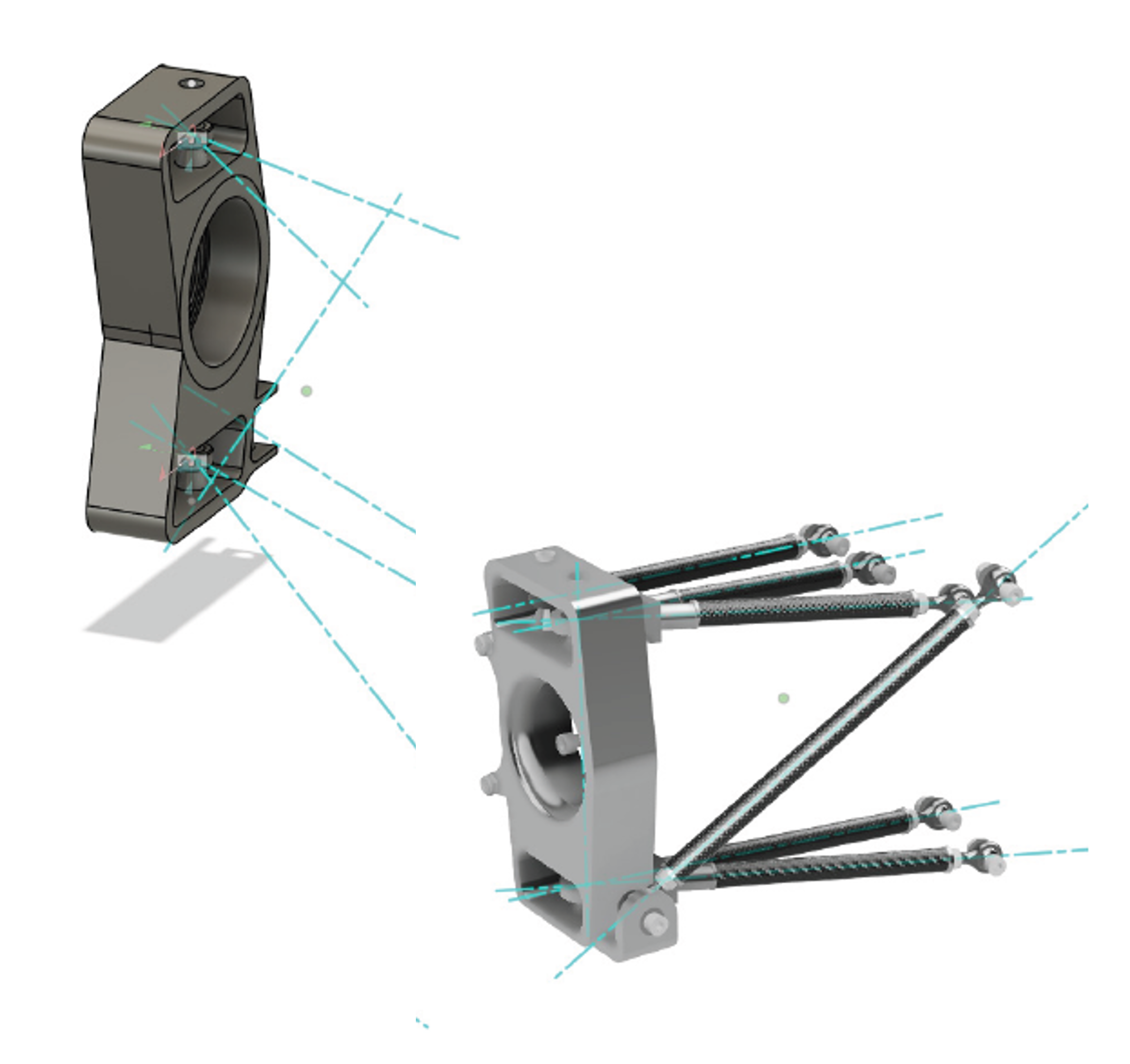
The suspension architecture was defined using chassis and upright pick-up points, creating a parametric foundation for rapid geometry development.
02
MATHEMATICAL MODELLING
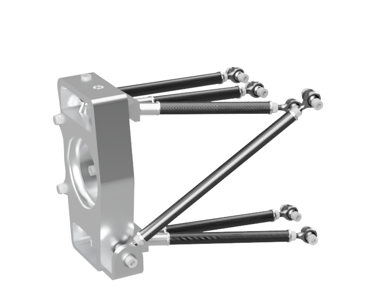
Mathematical representation of the final wishbone, pushrod and toe-link geometry allowed the suspension architecture to be assessed before detailed component development.
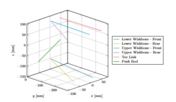
MATLAB representation of suspension hardpoints and link geometry.
Chassis and upright pick-up points were defined as the basis of the suspension architecture.
Wishbone, pushrod and toe-link positions were represented mathematically to understand wheel movement.
The resulting geometry informed detailed CAD development, packaging and subsequent structural validation.
03
STRUCTURAL DESIGN
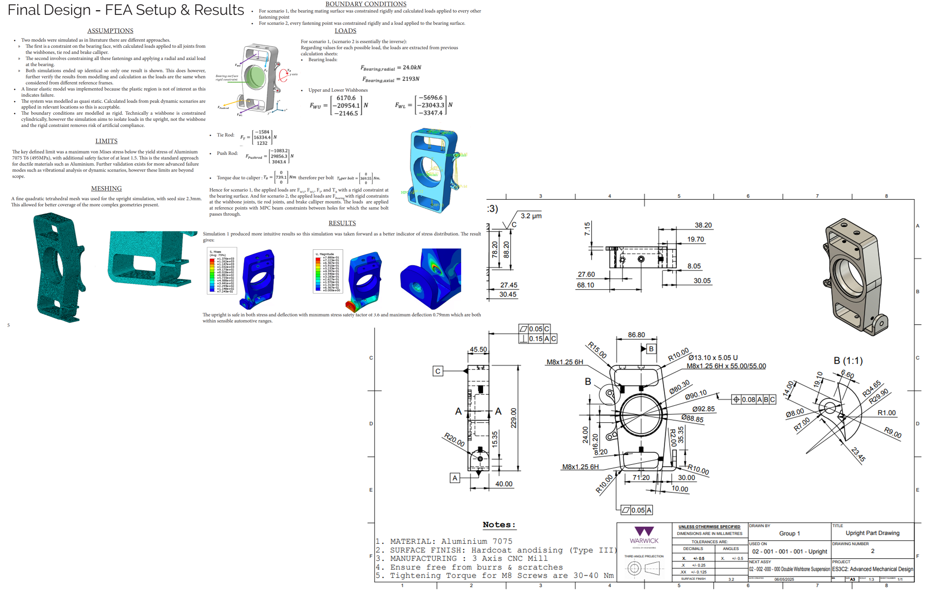
The upright was developed as a structural interface between suspension, wheel and braking systems while balancing stiffness, mass, packaging and manufacturing requirements.
DESIGN PHILOSOPHY
SYSTEM INTEGRATION
The suspension was developed alongside the wheel, brake, torque-transmission and wheel-hub systems to ensure the final design functioned as an integrated assembly.
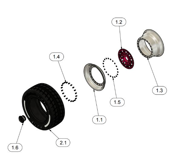
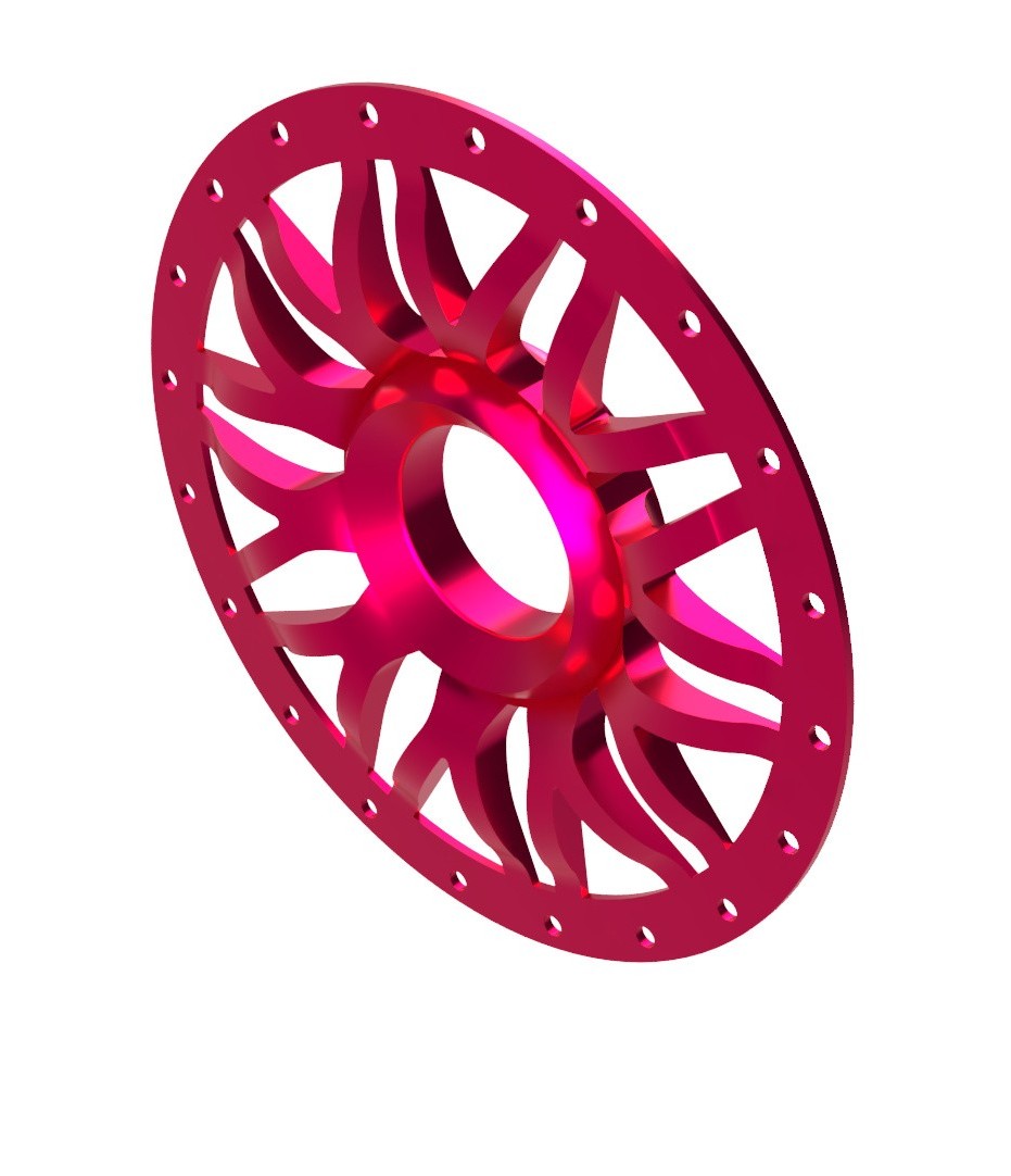
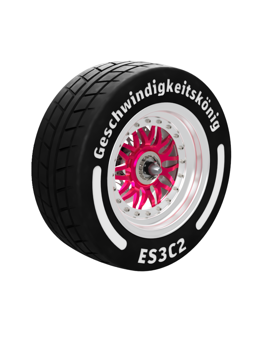
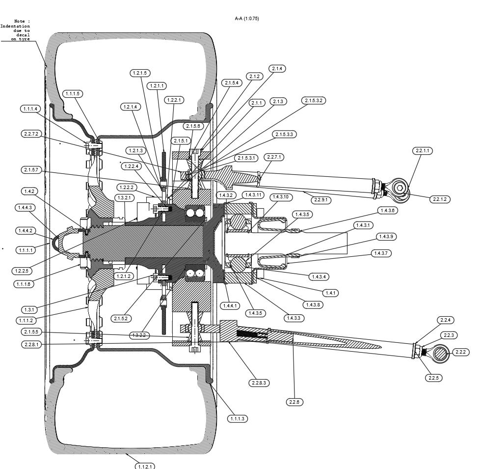
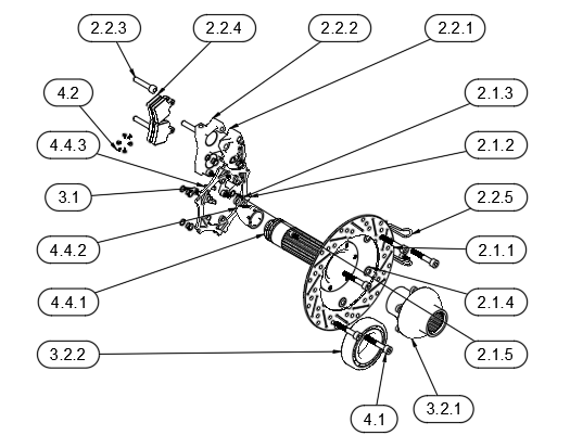
Detailed wheel assembly design including component architecture, manufacturing drawings and exploded assembly.
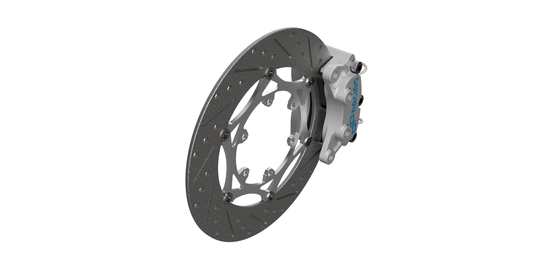
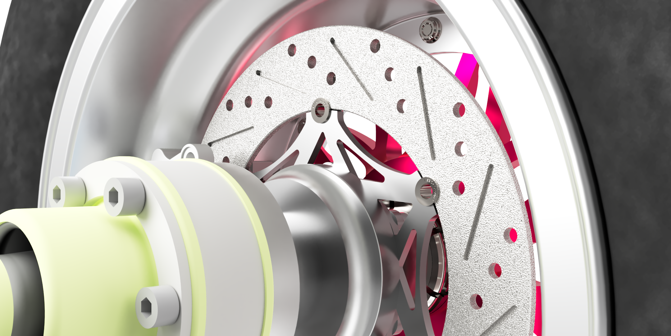
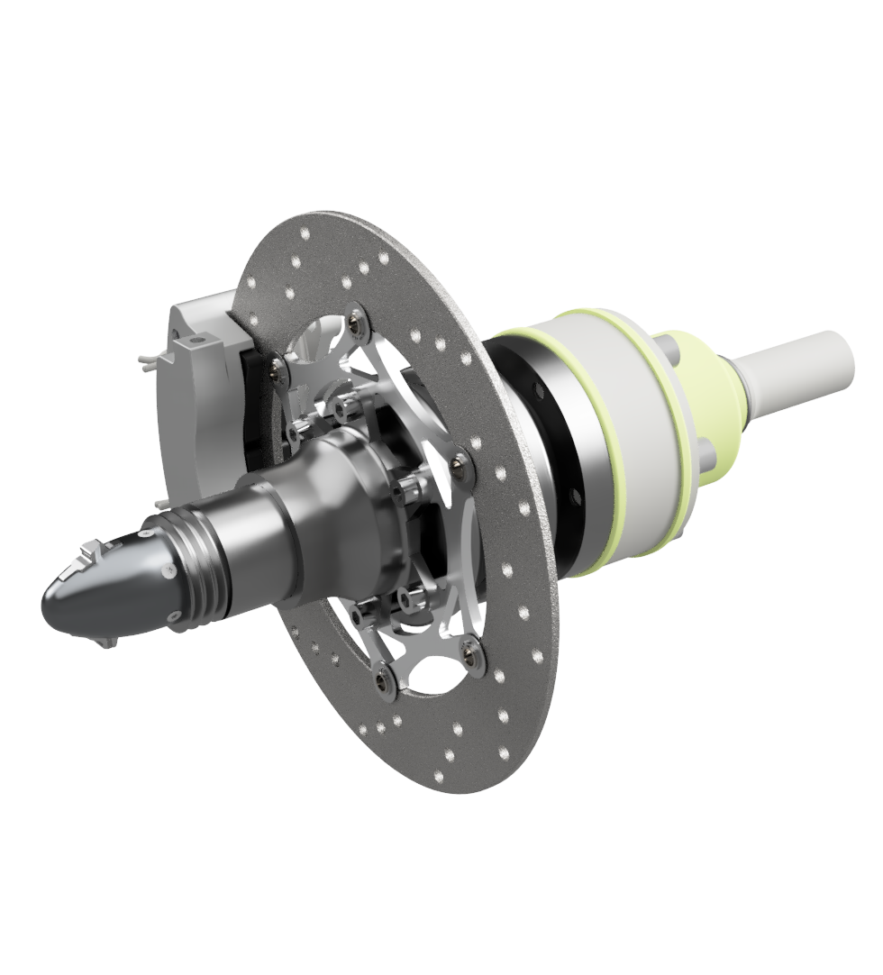
Brake disc and caliper integration developed around the suspension and wheel packaging envelope.
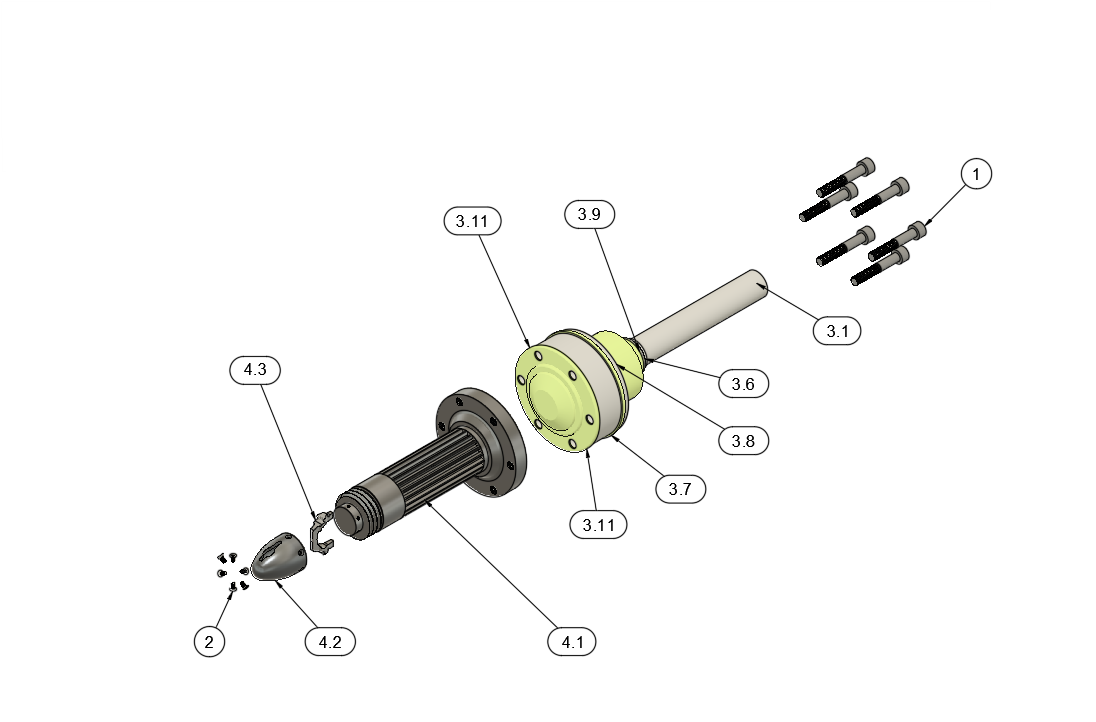
Transmission components designed to transfer drive torque through the hub while maintaining packaging and structural requirements.
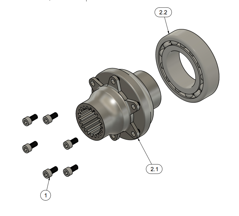
Wheel-hub design combining bearing interfaces, spline geometry and torque-transfer requirements.
08
MATLAB OPTIMISATION
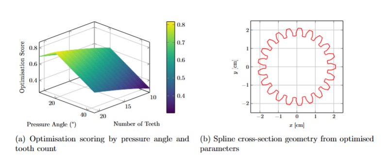
MATLAB-based modelling was used to optimise spline geometry before transferring the resulting geometry into detailed CAD.
09
COMPONENT DEVELOPMENT
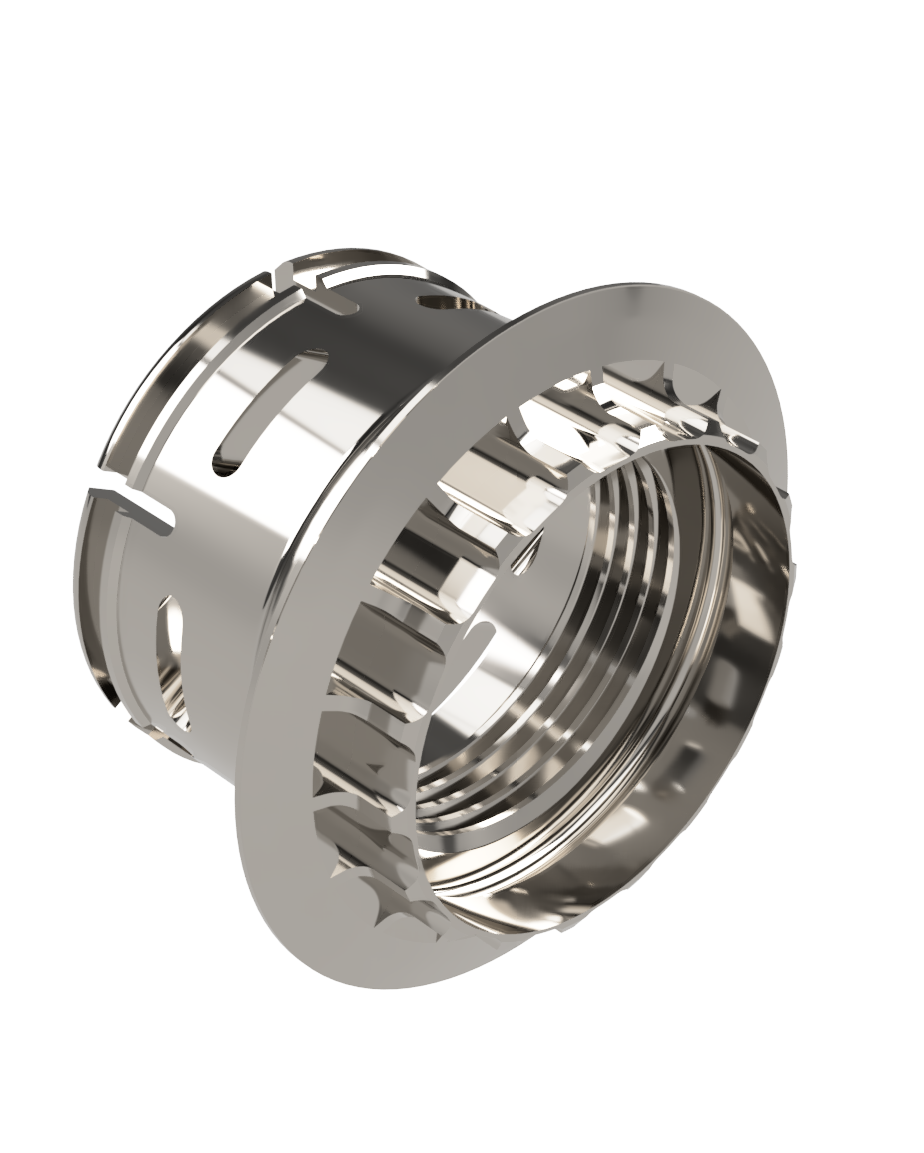
Individual components were developed and validated before being brought together within the complete rear-corner assembly.
10
FINAL INTEGRATION
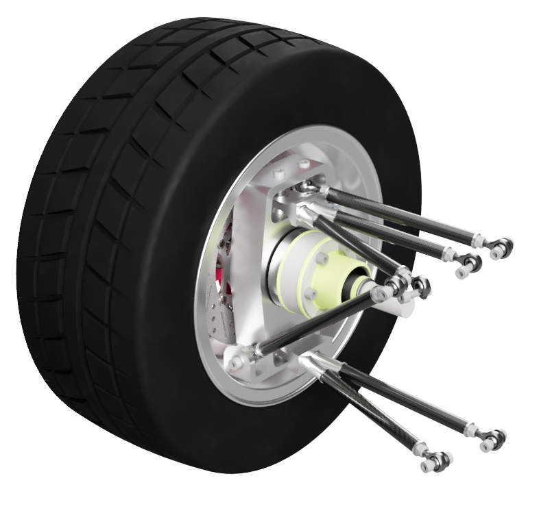
The final stage brought the suspension, upright, wheel, braking and torque-transfer systems together as one integrated rear-corner assembly.
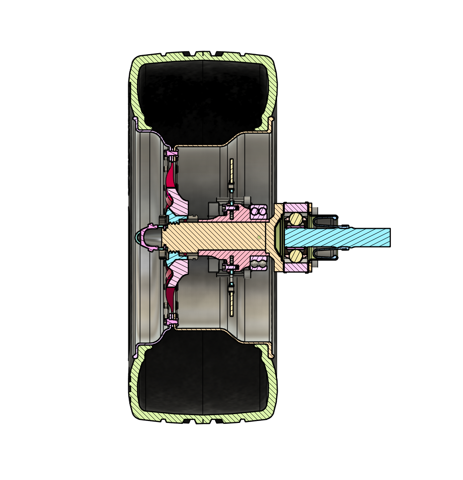
Cross-Section of Master Assembly
Integrated Suspension Assembly
PROJECT REFLECTION
This project developed my understanding of how analytical modelling, optimisation and detailed mechanical design can operate together within a single engineering workflow.
Rather than treating suspension components independently, the project required consideration of kinematics, load paths, packaging, structural behaviour, manufacturing and system integration throughout the design process.